
Honeywell Modutrol Master Class: Navigating the Series 90 to Series 70 Transition
The Industrial Standard for Proportional Actuation
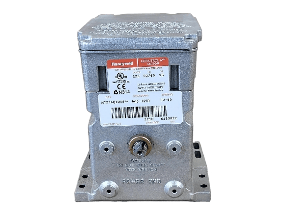
The Honeywell Modutrol series represents one of the most enduring legacies in industrial automation. Designated as a heavy-duty, spring-return or non-spring-return atmospheric actuator, the Modutrol motor is the primary component for controlling dampers, valves, and combustion air linkages in high-demand environments. Its prevalence is due to a robust NEMA-rated enclosure and a high-torque gear train that has remained physically consistent for decades.
However, the longevity of the Modutrol platform presents a complex challenge for contemporary system integration. While the physical mounting footprint has remained static, the internal control logic and feedback mechanisms have undergone multiple generational shifts. Today’s engineers are often tasked with replacing legacy Series 1, 2, or 3 hardware with modern Modutrol IV (Series 4) equivalents. This process requires more than a mere mechanical swap; it necessitates a rigorous evaluation of control signal impedance, power distribution, and auxiliary switch configurations to ensure system stability and prevent hardware failure.
Table of Contents
- →Cross-Reference: Series 90 to Series 70 Migration
- → Deciphering the Control Interface – Series 90 vs. Series 70
- → Critical Power Supply and Internal Transformer Specifications
- → Essential Modutrol Integration & Accessory Reference
- → Torque, Timing, and Suffix Specifications
- → Modutrol IV Suffix Decoder and Mechanical Matrix
- → Technical Selection Tip: Torque vs. Timing Trade-off
- → Technical FAQ: Field Engineering Solutions for Modutrol Installations
Cross-Reference: Series 90 to Series 70 Migration
| Series 90 Part # (Legacy) | Series 70 Replacement (Modern) | Torque (lb-in) | Fail-Safe (Spring) | Technical Migration Notes |
|---|---|---|---|---|
| M9184D1005 | M7284Q1009 | 150 | No | Standard NSR swap. M7284Q includes internal electronic positioner (4-20mA). |
| M9184A1035 | M7284Q1009 | 150 | No | Direct upgrade. Ensure 24VAC power is available for the Series 70 motor. |
| M9194D1003 | M7294Q1007 | 300 | No | High Torque: Heaviest NSR unit. Verify linkage integrity for 300 lb-in load. |
| M9174B1027 | M7284Q1009 | 150 (Upsize) | No | Legacy 75 lb-in motors are superseded by the modern 150 lb-in platform. |
| M9184D1021 | M7284Q1009 | 150 | No | Legacy 160° stroke. Modern Mod IV is field-adjustable for 90° or 160°. |
| M9164D1009 | M7284Q1009 | 150 | No | Standard Series 90 to 70 swap. Re-calibrate PID for new input impedance. |
For a more comprehensive cross reference guide, please see here: Honeywell Modutrol Motor Cross Reference Guide
Deciphering the Control Interface – Series 90 vs. Series 70

The most frequent complication in Modutrol replacement projects is a mismatch between the controller’s output signal and the motor’s input impedance. For decades, the Series 90 was the dominant architecture, utilizing a 135-ohm potentiometric (slidewire) control loop. In this configuration, the motor position is determined by a balancing bridge circuit across three specific terminals: W, R, and B. Because this is a mechanical resistance-based system, it is highly sensitive to wire length and terminal oxidation, but it remains prevalent in thousands of legacy burner and HVAC systems.
Modernization efforts typically shift toward the Series 70 protocol, which utilizes high-impedance electronic signals—most commonly 4-20mA or 2-10VDC. While a Series 70 motor, such as the M7284, may physically bolt onto the same linkage as an old M9184, the wiring logic is fundamentally different. A Series 70 motor requires a dedicated power supply (typically 24VAC) and uses a solid-state positioner to interpret current or voltage, rather than a resistive bridge. Attempting to drive a Series 70 motor with a Series 90 controller—or vice-versa—without the proper interface resistors or signal converters will result in an unresponsive actuator or a total failure of the control loop.
The following table serves as a definitive guide for identifying the control protocol and terminal requirements during a field audit or procurement phase.
| Feature | Series 90 (Legacy Standard) | Series 70 (Modern Electronic) |
|---|---|---|
| Control Signal | 135-Ohm Slidewire / Potentiometric | 4-20mA / 2-10VDC / 1-5VDC |
| Terminal Identifiers | W, R, B | T1, T2, F, G |
| Common Models | M9164, M9174, M9184, M9484 | M7284, M7285, M7294 |
| Power Requirements | Typically 24VAC or 120VAC | Primarily 24VAC (Requires Transformer) |
| Input Impedance | 135 Ohms (Fixed) | 100k Ohms (Voltage) / 250 Ohms (Current) |
| Signal Polarity | Non-Polarized Resistance | Polarity Sensitive (F = (+), G = (-)) |
| Feedback Option | Potential for 135-ohm feedback | 4-20mA Position Feedback available |
Critical Power Supply and Internal Transformer Specifications

One of the most frequent causes of premature actuator failure during a Series 90 to Series 70 migration is the mismanagement of supply voltage and grounding. Legacy Modutrol motors were frequently configured for 120VAC or 240VAC direct line voltage. In contrast, modern Modutrol IV Series 70 actuators are engineered primarily as 24VAC devices. Integrating these modern units into legacy high-voltage circuits requires a precise understanding of isolation and step-down requirements.
Failure to verify the internal transformer configuration can result in catastrophic damage to the solid-state drive board. When replacing an older line-voltage motor, the following technical requirements must be addressed:
-
Internal Transformer Integration: Modern Series 70 motors often require an internal transformer (such as the Honeywell 154073A) if they are to be powered by a 120VAC source. This transformer converts the line voltage to the 24VAC required by the motor’s logic board.
-
Isolation Hazards: In Series 70 applications, the control signal ground and the power supply ground must be handled with care. Using a non-isolated transformer to power multiple motors can create ground loops that distort the 4-20mA signal, leading to “hunting” or erratic positioning.
-
System Phasing: For installations utilizing multiple motors on a single transformer, proper phasing of the T1 and T2 terminals is mandatory. Out-of-phase wiring in a parallel configuration can cause a dead short across the secondary winding of the transformer.
-
Voltage Drop in Long Runs: Because Series 70 motors often operate on 24VAC, they are more susceptible to voltage drops over long wire runs than the older 120VAC models. Engineers must calculate the total VA (Volt-Ampere) draw—typically 13VA to 20VA per motor—to ensure the conductor gauge is sufficient to maintain at least 20.4VAC at the motor terminals under full load.
Essential Modutrol Integration & Accessory Reference
The following components are essential for reconciling power mismatches between legacy infrastructure and modern Modutrol IV hardware.
| Part Number | Component Description | Primary Application / Engineering Use |
|---|---|---|
| 220736A | Internal Auxiliary Switch Kit | Field-installable kit that adds two SPDT internal switches for position-based safety interlocking. |
| AT72D | External 40VA Transformer | A foot-mounted transformer used when an internal transformer cannot be used or when powering multiple motors. |
| Q607 / Q618 | Linkage Adapters | Adjusts for shaft height variances between legacy and modern motors to ensure alignment with fuel valves or dampers. |
| 4074ERU | Weather Shield (NEMA 3R) | Provides an environmental enclosure to protect motor terminals from direct precipitation and wash-down. |
| 7616BR | Heavy-Duty Weather Cover | Essential for NEMA 3R compliance in extreme outdoor environments; more robust than the standard shield. |
| 220741A | External Potentiometer Kit | Used to provide position feedback for remote monitoring in systems lacking a native Series 70 feedback signal. |
| 220738A | Adapter Bracket / Pedestal | Raises the motor height to match the center-line of legacy Series 1 and 2 actuators. |
| 27518 | Crank Arm (Driven) | Mounted on the valve or damper shaft to receive the force from the linkage rod. |
Torque, Timing, and Suffix Specifications
Beyond signal compatibility, the mechanical performance of a Modutrol actuator is defined by its Torque Rating and Timing (Stroke Speed). Selecting a motor with insufficient torque can lead to stalled gears or “chatter” against high-pressure dampers, while incorrect timing can destabilize a PID control loop, particularly in sensitive combustion air applications.
The Modutrol IV product line utilizes a standardized suffix system to denote these critical mechanical and electrical options. When performing a direct replacement, the suffix—the letter following the four-digit model number—is often more important than the base model itself. For example, an M7284Q and an M7284A are electrically similar but mechanically distinct in terms of their auxiliary switch configurations and internal positioners.
Key Specification Parameters:
-
Torque Capacity: Modutrol motors are categorized into three primary torque tiers: 75 lb-in, 150 lb-in, and 300 lb-in. It is a common engineering best practice to specify a motor with a 20% safety margin above the calculated load to account for linkage friction and aerodynamic “windage” on dampers.
-
Stroke Timing: The time required for the motor to travel from 0° to 90° or 160°. Standard timings include 30, 60, or 120 seconds. Rapid-response applications (like burner modulation) typically require 30-second motors, whereas slow-moving HVAC dampers may utilize 60- or 120-second versions to prevent pressure surges.
-
Spring Return vs. Non-Spring Return: * Spring Return (SR): Uses an internal mechanical spring to drive the motor to a “Fail-Safe” position (Open or Closed) upon loss of power.
-
Spring Return (SR): Uses an internal mechanical spring to drive the motor to a “Fail-Safe” position (Open or Closed) upon loss of power.
-
Non-Spring Return (NSR): The motor maintains its last position upon power failure.
-
-
Dual-Ended Shafts: Many modern Modutrol IV motors feature a “double-ended” shaft, allowing for auxiliary linkages or feedback potentiometers to be mounted on the rear of the motor, increasing installation flexibility in tight enclosures.
Modutrol IV Suffix Decoder and Mechanical Matrix
The following table provides a technical breakdown of the Honeywell suffix codes, allowing engineers to verify that the replacement hardware matches the functional requirements of the original installation.
| Suffix Letter | Primary Application | Timing (90° Stroke) | Auxiliary Switches | Notes |
|---|---|---|---|---|
| A | Non-Spring Return | 30 / 60 Sec | None | Basic proportional control. |
| C | Non-Spring Return | 30 / 60 Sec | 2 SPDT | Includes internal position-interlock switches. |
| D | Non-Spring Return | 15 / 30 Sec | None | High-speed version for rapid modulation. |
| F | Spring Return | 30 / 60 Sec | None | Fail-safe (Spring drives to 0° on power loss). |
| G | Spring Return | 30 / 60 Sec | 2 SPDT | Fail-safe with auxiliary position feedback. |
| Q | Electronic Modulating | 30 / 60 Sec | None | Modern Series 70 with built-in electronic positioner. |
Technical Selection Tip: Torque vs. Timing Trade-off
Note that torque and timing are inversely related through the internal gearing. A 300 lb-in motor will typically have a slower timing (60 seconds) compared to a 150 lb-in motor (30 seconds). If your application requires both high torque and high speed, verify the VA rating of your transformer, as these units draw significantly higher current during peak load.
Summary of Differences: The “Checklist”
Before finalizing a Series 70 order at TCI Supply, verify these three variables:
-
Does the application require Spring Return? (Failure to match this is a safety hazard).
-
Is the available power 24VAC or 120VAC? (Determines if an internal transformer is needed).
-
Are there auxiliary interlocks? (Determines if you need a “C” or “G” suffix motor with internal switches).
Technical FAQ: Field Engineering Solutions for Modutrol Installations
I am seeing “hunting” where the motor constantly oscillates around the setpoint. How do I stabilize a Series 70 loop?
Hunting is typically caused by a mismatch in the Requested Packet Interval (RPI) of the controller or high electrical noise on the 4-20mA line. Because Series 70 motors have high input impedance, they can pick up “ghost” voltages.
- The Fix: Install a 0.1 microfarad capacitor across terminals F and G to filter out high-frequency noise, or check the shield grounding of your signal cable. Ensure the shield is grounded at the controller end only to avoid ground loops.
Can I wire two Series 70 motors in parallel to a single 4-20mA signal?
Yes, but with a specific caveat. When wiring in parallel, the current signal is split, which will drop the voltage across the internal 250-ohm resistors.
- The Fix: You must wire the control signal in series (Output (+) to Motor 1 [F], Motor 1 [G] to Motor 2 [F], Motor 2 [G] back to Output (-)). However, the power supply (T1/T2) must remain in parallel. Ensure your controller can handle the combined 500-ohm load.
My legacy M9184 has a “Center-Tap” transformer. How do I reconcile this with a modern 24V M7284?
Older Series 90 systems occasionally used a 24V-0V-24V center-tapped transformer to drive the bridge.
- The Fix: Modern Modutrol IV motors cannot use a center-tap configuration. You must isolate the motor by installing a dedicated AT72D transformer or a 154073A internal transformer to provide a clean, two-wire 24V source that is independent of the rest of the legacy bridge circuit.
The new motor travels 90°, but my damper needs 160° for full dilution air. Is this a different part number?
In the legacy era, yes. In the modern Modutrol IV era, no.
- The Fix: Most Modutrol IV motors (like the M7284Q) are field-adjustable. By removing the top cover, you can adjust the internal cams. There is usually a blue or white plastic cam that can be rotated to switch the stroke from 90° to 160°. Always recalibrate your 4-20mA span in the controller after changing the mechanical stroke.
Why does my spring-return motor fail to close completely even though the spring is brand new?
This is often a “Windage” or “Back-Pressure” issue. If the damper is large, the air pressure against the blades acts as a counter-force to the spring.
- The Fix: Check the Crank Arm position. By shortening the radius of the crank arm on the motor shaft (moving the linkage pin closer to the center), you increase the mechanical advantage (torque) of the spring, allowing it to overcome the air pressure, though this will slightly reduce the total travel distance of the damper.
Conclusion: Precision Migration with TCI Supply
Navigating the transition from legacy Series 90 potentiometric systems to modern Series 70 electronic actuation is a critical step in plant modernization. While the physical hardware may appear identical, the success of your installation depends on the precise reconciliation of impedance, voltage, and mechanical torque.
At TCI Supply, we maintain a comprehensive inventory of both modern Modutrol IV actuators and the legacy accessories required to make your migration seamless. From internal transformers to signal-conversion resistors, our technical team is equipped to help you specify the exact Bill of Materials for your application.
Ready to specify your next Modutrol upgrade? Browse our Honeywell Modutrol Inventory or Consult with a TCI Technical Expert for a detailed cross-reference on your specific legacy part numbers.