
Why ASCO Valves Come With Different Electrical Connections
Understanding Suffix Variants, Wiring Configurations, and Sourcing Substitutes
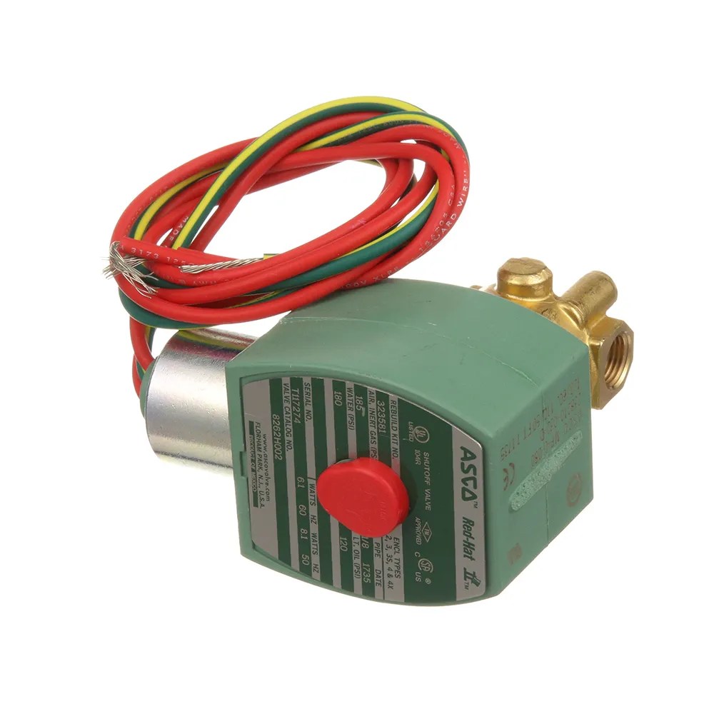
Most plants run on one electrical connection type. Once an engineer or maintenance team has standardized on hardwired conduit leads, DIN connectors, or junction boxes, that’s what they specify, and that’s what every valve in the plant uses. The choice usually reflects how the original panel was designed and what’s easiest for the electricians to maintain.
But there are real situations where a buyer needs to consider a different connection type, even on the same valve. The most common ones:
- Lead time and availability. The exact prefix you usually order is backordered ten weeks; the same valve with a different connection is on the shelf today. Substituting is often the difference between a line down today and a line back up tomorrow.
- Easier installation and replacement. DIN connectors plug onto the coil and disconnect with a single screw. For applications where valves are replaced regularly or where future service access matters, the quick-disconnect setup saves real time over hardwired conduit.
- Better ingress protection (IP) in washdown and harsh environments. A properly assembled DIN connector with its gasket compressed gives an IP65 / NEMA 4 watertight seal. For food, beverage, and pharma that’s a practical upgrade over flying leads run through conduit.
- Matching an existing panel spec. A control panel built around junction boxes or DIN connectors needs valves that match. When the original part isn’t available, knowing the substitute options keeps the existing wiring scheme intact.
Whichever situation applies, the underlying question is the same: when you change the electrical connection prefix on an ASCO valve, what actually changes, and how do you wire it? The answer is that the valve body, coil, voltage, watts, and flow capacity stay identical. Only the electrical termination changes, and each connection type has its own straightforward wiring procedure.
This guide walks through ASCO’s prefix system, the three connection types that determine how you wire the valve, and how to install each one. We’ll use the ASCO 8210G089 as our running example throughout. It’s one of the most common ASCO valves in industrial service (a 2-way, normally closed, 1/2-inch general-service valve), and the same prefix logic applies to every valve in ASCO’s catalog.
Table of Contents
How the ASCO Prefix System Works

Every ASCO valve catalog number has two parts: a prefix (sometimes none) and a base catalog number. The base catalog number identifies the valve itself, the body, function, voltage, watts, and flow capacity. The prefix identifies how the coil is electrically terminated.
The valve body, coil, and electrical ratings stay identical across prefix variants. Only the connection method changes. A no-prefix 8210G089, an SD8210G089, and a JKF8210G089 are all the same valve underneath, with the same coil and the same voltage and watts. The electrician just terminates the wires differently depending on the prefix.
The table below covers ASCO’s standard prefixes for general-service valves. The “Changes how you wire?” column flags which prefixes require a different installation procedure (covered in section 4) versus prefixes that only change the enclosure rating or coil temperature class.
| Prefix | Connection type | Changes how you wire? |
|---|---|---|
| (none) | 18-inch flying lead wires, conduit termination | — (the default) |
| L | 72-inch flying lead wires, conduit termination | No (same as no-prefix, longer leads) |
| HT, HB | 18-inch leads, high-temperature Class H coil | No (same wiring, higher-rated coil) |
| HTL, HBL | 72-inch leads, high-temperature Class H coil | No |
| SC, SD | DIN 43650 Form A connector | Yes |
| SU, SV | DIN 43650 Form A, high-temperature Class H | Yes (same as SC/SD wiring) |
| JKF, JKP | Junction box with screw terminals | Yes |
| JSF, JSP | Junction box with 1/4-inch spade terminals | Yes |
| JKH, JKB | Junction box screw terminals, high-temperature | Yes (same as JKF wiring) |
| JSS, JST | Junction box spade terminals, high-temperature | Yes (same as JSF wiring) |
| OFKF, OFKP | Open-frame coil with screw terminals | Yes |
| OFSF, OFSP | Open-frame coil with spade terminals | Yes |
| EF | Explosionproof housing, conduit termination | No (same as no-prefix, hazardous-location enclosure) |
| EV | Explosionproof, corrosion-resistant housing | No |
| EFL | Explosionproof, 72-inch leads | No |
- Some prefixes only differ in coil temperature class. The standard Class F coil prefixes (no-prefix, SC, JKF, JSF, etc.) and their Class H high-temperature equivalents (HT, SU, JKH, JSS, etc.) wire identically. If you’re substituting between a Class F and a Class H variant of the same connection type, the installation doesn’t change.
- Explosionproof prefixes (EF, EV, EFL) change the enclosure, not the wiring. Inside an explosionproof housing, the coil still terminates to flying leads run through conduit, the same as a no-prefix valve. Installation in a hazardous location follows your local electrical code for those environments, but the wiring procedure itself doesn’t change.
- Three connection types require a genuinely different wiring procedure: DIN connectors (SC, SD, SU, SV), junction boxes (JKF, JSF, and their variants), and open-frame terminals (OFKF, OFSF, and variants). Section 4 walks through how to wire each one.
- Please find all of the Asco Valve Optional Features here.
Wiring Each Connection Type, Step by Step

This section covers the connection types that change how you wire the valve. The three that matter for installation are DIN connectors (SC, SD, SU, SV prefixes), junction boxes (JKF, JSF, and variants), and open-frame terminals (OFKF, OFSF, and variants). Flying-lead wiring (no-prefix, L, HT) gets a brief baseline first since it’s the default most electricians already know.
For any connection type, the same safety prerequisites apply: confirm power is locked out at the source, verify the valve coil voltage matches the line voltage, and use field wire rated for the temperature class of your installation (90°C minimum for standard service, 105-125°C for steam service).
Flying lead wires (no prefix, L, HT, HB)
The default ASCO connection. The coil ships with two 18-inch (no prefix) or 72-inch (L) leads plus a green or green-with-yellow-stripe ground wire, all exiting through a 1/2-inch conduit hub on the coil. To install:
- Run conduit to the 1/2-inch hub on the coil housing.
- Pull the leads through the conduit to the panel or junction box.
- Connect line and neutral (or + and − on DC) to the corresponding circuit terminals; AC valves are non-polarized so lead orientation doesn’t matter.
- Bond the green ground wire to ground in the panel.
- Verify the conduit hub is sealed against moisture if the installation is exposed.
DIN 43650 Form A connectors (SC, SD, SU, SV)

The SC and SD prefixes (and their Class H equivalents SU, SV) ship the valve with a rectangular DIN plug connector that plugs onto three pins protruding from the top of the coil. The connector housing contains an internal terminal block with screw terminals for line, neutral, and ground.
DIN connectors are common in food and beverage, pharmaceutical, and washdown environments because the properly assembled plug with its gasket gives IP65 / NEMA 4 watertight protection. They’re also a favorite where future serviceability matters: future valve replacements just need the center screw loosened and the plug pulled. To install the plug onto a new SD or SC valve:
- Disassemble the DIN plug. Back the center screw out completely, then gently pry the internal terminal block out of the plastic housing with a small flathead screwdriver. Loosen the cable gland nut at the back of the housing.
- Feed the cable through the housing. Strip about 1/4 inch of insulation off each wire. Pass the cable through the gland nut and the outer housing before landing it on the terminal block.
- Land the wires on the terminal block. The terminals are labeled 1, 2, and a ground symbol (⏚).
- For AC power (120V or 240V): Hot to terminal 1, neutral to terminal 2, green ground to the ground terminal.
- For DC power (24V DC): Positive (+) to terminal 1, negative (−) to terminal 2, ground to the ground terminal.
- Tighten the terminal screws and pull-test each wire to confirm secure connection.
- Reassemble the housing. Slide the terminal block back into the housing until it clicks. The block can be oriented in 90-degree increments so the cable exits in the direction that works for the installation (downward to avoid hot pipes, away from the panel, etc.).
- Tighten the cable gland nut around the cable to seal the rear of the housing.
- Place the rubber gasket over the three pins on top of the coil. Do not skip the gasket; without it, the connection isn’t watertight.
- Press the plug onto the coil pins and insert the long center screw. Hand-tighten with a screwdriver to compress the gasket. Do not over-torque, the plastic housing will crack before the gasket is over-compressed.
The result is a watertight, quick-disconnect electrical connection that comes apart in seconds for future service.
Junction box terminals (JKF, JKP, JSF, JSP, and high-temp variants)
Junction box prefixes ship the valve with a small metal junction box mounted directly to the coil, with a 1/2-inch conduit hub for incoming field wires. Inside the box are either screw terminals (JK- prefixes) or 1/4-inch spade lugs (JS- prefixes) for landing the wires.
Junction boxes are used where electricians prefer terminated wiring over plug-in connectors, where the installation needs a serviceable terminal point inside an enclosure, or where standardization across a plant requires every valve to have a junction box. NEMA 4 rated when properly installed. To install:
- Open the junction box cover by removing the cover screws.
- Run conduit to the 1/2-inch hub on the side of the junction box.
- Pull field wires through the conduit into the junction box. Use #12-#18 AWG stranded copper rated for 90°C or higher (105-125°C for steam service).
- Land the wires:
For screw terminals (JKF, JKP, JKH, JKB): Strip 1/4 inch of insulation. Land hot/positive on terminal 1, neutral/negative on terminal 2. Torque terminal screws to 10 ± 2 in-lbs.
For spade terminals (JSF, JSP, JSS, JST): Crimp 1/4-inch female spade lugs onto each wire. Slide the spade lugs onto the corresponding terminal blades. - Bond the ground wire to the grounding screw provided inside the junction box. Torque the grounding screw to 15-20 in-lbs.
- Close the junction box cover and confirm the cover gasket is seated for NEMA 4 protection.
Open-frame terminals (OFKF, OFKP, OFSF, OFSP)
Open-frame prefixes ship the coil with bare screw or spade terminals and no enclosure. These coils are not intended for standalone installation, they go inside another panel, valve manifold, or OEM enclosure that provides the environmental protection.
Wiring is essentially the same as the inside-the-junction-box procedure for JKF or JSF, just without the surrounding junction box. Strip and land wires on the terminals (screw or spade), bond the ground to the coil’s grounding screw, and rely on the surrounding enclosure for NEMA rating.
Because open-frame coils have no enclosure, they’re typically specified by OEMs and panel builders who are integrating the valve into a larger system. If you’ve received an open-frame coil as a substitute for an enclosed version, confirm with the panel design before installing, since the surrounding enclosure needs to provide the protection the coil itself doesn’t.
A Worked Example: Substituting an SD8210G089 for an 8210G089

Here’s exactly the situation we run into on the sales floor. A maintenance buyer needs an ASCO 8210G089 for a process line. We don’t have the no-prefix 8210G089 in stock, the lead time from ASCO is 10 weeks, and the line is down. But we do have an SD8210G089 on the shelf, ready to ship today.
Is the SD version an acceptable substitute? Almost always, yes. Here’s how to walk through that decision and what the electrician needs to do once the valve arrives.
Step 1: Confirm the valve specs match – The first job is verifying that the valve itself is the same valve, just with a different electrical connection. Compare the two part numbers side by side. If everything matches except the electrical connection, the substitution is safe. The valve will function identically; only the wiring procedure changes.
Step 2: Verify the voltage on the actual valve – This is the one verification that has to happen on the physical valve, not just on paper. Read the voltage label on the SD8210G089 coil and confirm it matches the line voltage at the installation. ASCO coils must match the line voltage exactly, regardless of the connection type. A 120V coil won’t run on 24V DC, and a 240V coil won’t run on 120V AC. Connection prefix variants are interchangeable; voltage variants are not.
Step 3: Plan the wiring transition – The original installation used 18-inch flying leads run through 1/2-inch conduit to the control panel. The SD8210G089 ships with a DIN 43650 plug connector instead. The electrician has two paths:
- Option A (simpler): Wire the new DIN plug onto the existing conduit cable. The existing conduit and field wiring stay in place. The electrician removes the no-prefix coil (or replaces the whole valve), receives the SD valve with the DIN plug, disassembles the plug, lands the existing conduit cable on the DIN plug’s terminal block (using the procedure in section 3), reassembles the plug, and presses it onto the new coil’s pins. The conduit run never changes. Total time: usually 15-20 minutes.
- Option B (cleaner long-term): Pull new flexible cable from the panel and terminate at the DIN connector. If the existing conduit is in a poor location or the buyer wants to take advantage of the DIN connector’s quick-disconnect feature for future service, the electrician can run a new cable directly to where the valve sits. This is more work today but pays off the next time the valve needs service.
For most stop-the-bleeding substitutions, Option A is the right call. The DIN plug just becomes the new termination point at the end of the existing conduit run.
Step 4: Install and verify – With the plug wired (per the section 3 DIN procedure), the electrician mounts the SD8210G089 in place of the old valve, plugs the wired DIN connector onto the coil pins with the gasket seated, and tightens the center screw. The system gets re-energized, the valve cycles on a test signal, and the substitution is complete.
What if the substitute was a JKF8210G089 (junction box) instead?
Same logic, different wiring procedure. The substitute valve arrives with a junction box mounted on the coil. The electrician:
- Verifies the same specs in the table above (voltage, watts, Cv, body, pipe size).
- Routes the existing conduit cable into the 1/2-inch hub on the side of the junction box.
- Lands the wires on the screw terminals inside the box (or crimps spade lugs onto the wires for a JSF spade-terminal version).
- Bonds ground to the junction box’s grounding screw.
- Closes the cover.
What if the substitute was an OFKF8210G089 (open-frame) instead?
This one needs more thought before accepting the substitute. An open-frame coil has no enclosure of its own, so it’s only appropriate if the installation already provides one (the valve is going inside a sealed control cabinet, manifold block, or OEM enclosure). For most plant-floor installations with valves exposed to ambient conditions, an open-frame substitute is not equivalent to an enclosed valve; the buyer should pass on this substitute and either wait for the original or find a different enclosed-coil alternative.
If the installation does provide an enclosure (panel-builder context, manifold mounting, OEM equipment), the electrician lands the wires directly on the coil’s screw or spade terminals, bonds ground, and relies on the surrounding enclosure for protection.
When You Can Substitute Prefixes (and When You Can’t)
The good news for purchasing managers: prefix substitutions are usually safe. The valve body, coil, and electrical ratings stay identical across prefix variants of the same base catalog number. What changes is the wiring termination, which the electrician handles at install time.
The not-so-good news: a substitution is only equivalent if everything except the prefix matches. Get one of the other specs wrong and you’re substituting a different valve, not just a different connection type.
The five specs that must match
Before accepting any prefix substitution, confirm these five specs match between the original and the substitute:
| Spec | Why it must match |
|---|---|
| Base catalog number | Identifies the valve body, function, and orifice. Different base number = different valve, not a substitution. |
| Voltage | Coils are voltage-specific. A 120V AC coil won’t run on 24V DC and vice versa. Read the actual coil label, not just the catalog number. |
| Watts | Higher-wattage coils generate more heat and may exceed your installation’s temperature rating. Same-watt substitutions are safe. |
| Cv (flow coefficient) | Determines flow capacity at a given pressure drop. Different Cv = different valve sizing for your application. |
| Body material and pipe size | Brass, stainless, aluminum, or other body materials interact differently with process media. Pipe size must match the existing piping. |
What can differ without affecting the substitution
These can differ between original and substitute without compromising the install:
- Electrical connection prefix (the whole point of this article)
- Coil temperature class (Class F vs Class H, as discussed in section 2)
- Lead length (18-inch vs 72-inch flying leads)
- Enclosure rating from EF/EV prefixes, provided your installation environment doesn’t require explosionproof certification. If the original spec called for an EF or EV valve because the installation is in a hazardous location, you must substitute with another EF/EV valve. You can’t drop a non-explosionproof valve into a Class I hazardous location regardless of how well it’s wired.
When to pass on a substitution
A few situations where the substitute isn’t equivalent and the buyer should hold out for the original:
- Different voltage on the coil label. Not a substitution; it’s a different valve. Pass.
- Open-frame (OF) substitute for an enclosed installation. Open-frame coils require an external enclosure. If your installation doesn’t already provide one, pass.
- Non-explosionproof substitute for an EF/EV original when the installation is in a hazardous location. The original EF/EV designation reflects a code requirement, not a preference. Pass.
- Different Cv or pipe size, even if everything else matches. The valve will physically fit but won’t perform the same. Pass.
The bottom line for purchasing
If the original part is on a long lead time and a different-prefix variant is on the shelf, the substitution is almost always safe as long as the five specs above match. The electrician’s install procedure changes (per the wiring steps in section 3), but the valve does its job identically. For high-volume parts like the 8210G089, prefix-variant substitution is a routine sourcing tactic that keeps lines running while waiting for the exact preferred prefix to come available.
Sourcing ASCO Valves From TCI Supply
Whether you need the exact prefix you originally specified, an acceptable substitute that ships today, or help working through whether a substitution is genuinely equivalent for your installation, the starting point is the same: send us your part number and your situation.
Sourcing ASCO solenoid valves is core to what we do. The 8210G series in particular (along with the 8262, 8220G, 8030G, and other workhorse general-service families) is something we stock across multiple prefix variants because real plants need real options when lead times get long. If we have the exact prefix you want, you get it. If we don’t, we can usually offer a prefix-variant substitute that ships today and walk through with you whether it works for your application.
Send us your ASCO valve part number, your line voltage, your installation environment, and any specs that matter for your application. We’ll confirm what’s available, identify equivalent substitutes if needed, and get you a quote. Whether you need an exact 8210G089 on a planned shutdown, an SD8210G089 to keep a line running today, or help speccing the right valve for a new build, contact TCI Supply or call us at 1-800-755-2883.