 1769 CompactLogix by Allen Bradley – Buyer’s Guide
In this guide, we will learn all about the Allen Bradley 1769 CompactLogix series of PLCs – which parts to buy, how to assemble the input and output modules into the slot rack, and troubleshooting any issues.
The Allen-Bradley 1769 CompactLogix series by Rockwell Automation is a popular line of programmable logic controllers (PLCs) designed for mid-size control applications that require reliable performance, modular flexibility, and seamless integration. These PLCs are known for combining the power of Logix control with a compact, space-saving footprint, making them ideal for both standalone machine-level control and small system applications. Engineers commonly use the CompactLogix series in industries like manufacturing, food and beverage, packaging, material handling, and even in smaller process control environments. Their modular design allows for easy expansion with I/O and communication modules, enabling users to scale systems as needed.
CompactLogix PLCs are typically programmed using Rockwell’s Studio 5000 Logix Designer software, which provides a unified development environment for programming, testing, and commissioning. These controllers support communication protocols such as EtherNet/IP, and are often used alongside compatible Allen-Bradley 1769 I/O modules, PanelView HMIs, and PowerFlex drives. Their versatility makes them a popular choice for engineers looking to standardize control architecture across multiple systems while maintaining the flexibility to customize control strategies for specific machine or process requirements.
For the Allen Bradley 1756 ControlLogix guide, click here.
 Essential Components of a CompactLogix PLC Rack
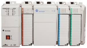
When designing an Allen-Bradley 1769 CompactLogix PLC system, please follow the below parts breakdown. Unlike other traditional rack-based PLC series , CompactLogix uses a modular, chassis-less design where modules connect side-by-side using interlocking plugs and connectors. Here’s how the system is typically structured:
1. Processor / CPU Module
-
Role: The brain of the system—executes the user program, handles logic, communication, and I/O control.
-
Common Part Numbers:
-
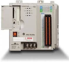
1769-L24ER-QB1B – Controller with embedded I/O and Ethernet port.
-
1769-L35E – Modular controller with Ethernet communication.
-
1769-L33ER – More modern version supporting higher memory and connectivity.
-
2. Power Supply
-
Role: Provides power to the processor and connected I/O modules. Not all modules need dedicated power supplies, but larger systems often benefit from separate power distribution.
-
Common Part Numbers:
-
1769-PA4 – AC power supply (85-265V AC input).
-
1769-PB4 – DC power supply (19.2-31.2V DC input).
-
3. Input Modules
-
Role: Receive signals from sensors or other field devices and relay them to the processor.
-
Common Part Numbers:
4. Output Modules
-
Role: Send control signals from the processor to actuators, solenoids, relays, lights, or other devices.
-
Common Part Numbers:
-
1769-OB16 – 16-point 24V DC output module.
-
1769-OB32 – 32-point digital output module.
-
1769-OF4CI – 4-channel analog output module with current/voltage output.
-
5. Communication Modules
-
Role: Enable the CompactLogix controller to connect with external devices, HMIs, drives, or remote I/O over industrial networks.
-
Common Part Numbers:
-
1769-AENTR – Ethernet/IP adapter for remote I/O.
-
1769-SDN – DeviceNet scanner module.
-
1769-ECR / 1769-ECL – End caps for right or left expansion (required for communication and proper system closure).
-
6. Specialty Modules
-
Role: Provide specific functionality such as motion control, high-speed counting, or data handling.
-
Common Examples:
-
1769-HSC – High-speed counter.
-
1769-ASCII – ASCII communication module.
-
7. Expansion / End Modules
-
Role: Required to complete the system’s electrical and communication path. Also used when extending the system with additional banks of modules.
-
Common Part Numbers:
-
1769-ECR – Right end cap (required at the end of each I/O bank).
-
1769-ECL – Left end cap (if not attaching to a controller).
-
Notes on Configuration:
-
Each CompactLogix system has limits on the number of I/O modules it can support based on power supply and controller model.
-
Modules are mounted side-by-side in a specific sequence: controller, power supply, I/O, communication, then end caps.
Step-by-Step Guide to Building a 1769 CompactLogix PLC Rack
1. Define Your System Requirements
Before selecting parts, determine the needs of your application:
-
How many inputs and outputs?
-
What types of signals (digital/analog)?
-
Which communication protocols are required (EtherNet/IP, DeviceNet, etc.)?
-
Any specialty needs? (high-speed counting, motion, etc.)
2. Select Your Processor (Controller)
Choose a CompactLogix CPU based on:
-
Memory size needed.
-
Number of I/O points and modules.
-
Communication ports required.
Example Choices:
-
1769-L24ER-QB1B (with built-in I/O and Ethernet)
-
1769-L33ER (modular with Ethernet, 2 MB memory)
-
1769-L32E (classic model with Ethernet and serial)
3. Choose a Power Supply
Power supply must match the system’s total load:
-
Count all modules and their current draw.
-
Choose AC or DC input as required.
Common Options:
-
1769-PA4 – AC input.
-
1769-PB4 – DC input.
4. Select I/O Modules
Add the required number and type of I/O modules.
Digital Input:
-
1769-IQ16 (16-point 24V DC input)
Digital Output:
-
1769-OB16 (16-point 24V DC output)
Analog I/O:
-
1769-IF4 (4-channel analog input)
-
1769-OF4CI (4-channel current/voltage output)
Tip: Group similar modules to simplify wiring and diagnostics.
5. Add Communication Modules (if needed)
For external device communication or remote I/O:
Examples:
-
1769-AENTR – EtherNet/IP adapter
-
1769-SDN – DeviceNet scanner
-
1769-ASCII – ASCII serial module
6. Add End Caps and Expansion Modules
These finalize and maintain the backplane connection.
Required:
-
1769-ECR – End cap for the right side (always required).
-
1769-ECL – End cap for the left side (if controller not first).
7. Physically Assemble the Rack
Here’s how to build it:
-
Mount DIN rail or back panel.
-
Attach modules side-by-side, left to right:
-
Start with the controller (if not embedded).
-
Next, power supply.
-
Then, I/O and comms modules.
-
Finish with the ECR end cap.
-
-
Use the interlocking connectors—no chassis needed.
Each module snaps in and connects through the backplane connector on its side.
8. Apply Power and Check LEDs
-
Ensure power is stable.
-
Check status LEDs on controller and I/O modules.
-
Resolve any faults before continuing.
9. Connect to Studio 5000 Logix Designer
-
Plug in via USB or Ethernet.
-
Open Studio 5000 software.
-
Create a new project matching your controller part number.
-
Download the program, configure modules, and test I/O.
10. Label and Document the Setup
-
Label each I/O point and module.
-
Document addresses, wiring, and layout for future maintenance.
Testing and Maintenance of a ControlLogix PLC Rack
Testing and maintaining a 1769 CompactLogix PLC rack is essential to ensuring system reliability and long-term performance. After initial installation, engineers should verify that all modules are properly seated and secured, and confirm communication status using LED indicators. Input and output modules should be tested with real-world signals to validate proper field wiring and logic execution. Using Rockwell’s Studio 5000 Logix Designer software, users can monitor live data, force I/O points, and troubleshoot any errors or faults.
Routine maintenance includes periodic inspection of connectors, power supplies, and environmental conditions like temperature and dust. It’s important to back up the PLC program regularly and document any changes made during commissioning or upgrades. Firmware updates should be scheduled during downtime and verified for compatibility before installation.
Additionally, engineers should check for signs of wear or damage on I/O terminals and monitor system diagnostics within the controller to identify potential issues early. Keeping spare modules on hand can reduce downtime in the event of a failure. Proper testing and preventative maintenance help avoid costly breakdowns and ensure system uptime in demanding industrial environments.
Troubleshooting common 1769 Compactlogix PLC Rack Issues
-
Verify Power Supply: Confirm that the correct voltage is supplied and that all power connections are secure.
-
Inspect LED Indicators: Check status and fault LEDs on the CPU, I/O, and power supply modules for error signals.
-
Module Seating and Connection: Ensure all modules are firmly seated in the backplane and properly interconnected.
-
Examine Wiring: Review field wiring at input/output terminals for loose connections or incorrect wiring.
-
Network Configuration: Check Ethernet/IP or other communication settings for address conflicts and proper configuration.
-
Firmware and Software: Validate that the firmware on the controller is up-to-date and compatible with the Studio 5000 Logix Designer project.
-
Diagnostics and Test Routines: Use Studio 5000 to run diagnostics, force I/O states, and monitor live data for irregularities.
-
Environmental Conditions: Inspect for signs of overheating, dust, or moisture that could affect module performance.
-
Document Issues: Record error codes and troubleshooting steps taken to aid future maintenance and problem resolution.
-
Spare Parts Availability: Ensure that critical spare modules or connectors are available to minimize downtime during replacements.
Building a 1769 CompactLogix PLC Rack – Frequently Asked Questions
What are the best CompactLogix modules for high-speed applications?
For high-speed applications, use the 1769-HSC (High-Speed Counter) module and a processor with fast scan times like the 1769-L33ER. Also, ensure your I/O modules support fast response times—digital modules like 1769-IQ16 and 1769-OB16 are commonly used.
How to ensure data security when setting up a CompactLogix PLC rack?
Use user accounts with role-based access in Studio 5000, enable controller password protection, and configure firewalls and managed switches on the network. Limit who has upload/download access and keep firmware up to date.
Can I upgrade an existing PLC rack to a CompactLogix system?
Yes, but it requires rewriting the program in Studio 5000, and replacing hardware with CompactLogix-compatible modules. Check I/O wiring and panel space, as CompactLogix uses a different physical format than older SLC or PLC-5 systems.
How do I choose the right processor for my CompactLogix rack?
Base your choice on the I/O count, memory requirements, and communication needs. For simple systems, 1769-L24ER may suffice; for more demanding applications, go with 1769-L33ER or L35E. Always leave room for system growth.
How often should I perform maintenance on my CompactLogix PLC rack?
Perform visual inspections monthly and do a full maintenance check every 6–12 months. Look for loose wiring, clean dust buildup, check LED indicators, and back up your program regularly. Monitor system diagnostics via Studio 5000.
