A Guide to Essential Parts and Assembly: Building a Controllogix PLC Rack

In this guide, we will learn all about the Allen Bradley 1756 ControlLogix series – which parts to buy, how to assemble the input and output modules into the slot rack, and troubleshooting any issues.

Allen-Bradley PLC systems, manufactured by Rockwell Automation, are among the most widely used programmable logic controllers (PLCs) in industrial automation. Known for their reliability, scalability, and integration capabilities, these controllers serve as the backbone of modern manufacturing, process control, and discrete automation systems. The 1756 ControlLogix series stands out as Allen-Bradley’s flagship PLC platform, designed to handle complex automation tasks with high-speed processing, modular flexibility, and seamless integration with Rockwell’s EtherNet/IP and FactoryTalk ecosystems. ControlLogix PLCs offer enhanced data handling, motion control, and safety functionality, making them ideal for industries ranging from oil & gas and power generation to food processing and automotive manufacturing. Their redundant, high-availability architectures and expandable I/O configurations provide engineers with the tools to build scalable, future-proof control systems while reducing downtime and improving operational efficiency.

Shop Our Industrial and Commercial PLCs

Essential Components of a ControlLogix PLC Rack

When building a ControlLogix PLC automation rack, several key components are required to ensure a reliable and efficient control system. Below is a breakdown of the essential parts and their roles:

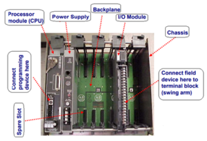
  • ControlLogix Chassis (Example – 1756-A13)

    • The backbone of the system, providing a mounting structure for all modules.
    • Available in different slot configurations (e.g., 4-slot, 7-slot, 10-slot, 13-slot, 17-slot) to accommodate system size and expansion needs.
    • Provides the backplane for communication between installed modules.
  • Power Supplies (Examples – 1756-PA751756-PB721756-PSCA2)

    • Supplies regulated power to the chassis and installed modules.
    • Available in AC (120/240V) and DC (24V, 48V) models to match plant power requirements.
    • Redundant power supply options (1756-PSCA2) available for high-availability applications.
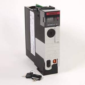
  • Control Processor (1756-L85E1756-L721756-L61 )

    • The CPU (Programmable Automation Controller) responsible for executing control logic, managing I/O, and handling communication.
    • Features high-speed processing, embedded motion control, and support for extensive tag-based programming.
    • Newer 1756-L8x series offers enhanced security, increased processing speed, and improved memory capacity.
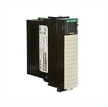
  • I/O Modules (1756-IA161756-IB161756-OF8)

    • Digital Input Modules – Interface with discrete sensors and switches (e.g., 24V DC, 120V AC).
    • Digital Output Modules – Control relays, solenoids, and indicator lights.
    • Analog Input Modules – Process signals from pressure transducers, thermocouples, and flow sensors.
    • Analog Output Modules – Control variable speed drives, proportional valves, and other analog-driven actuators.
  • Communication Modules (1756-EN2T1756-CN21756-DHRIO)

    • EtherNet/IP (1756-EN2T, 1756-EN4TR, etc.) – Standard for high-speed industrial network communication, used for SCADA integration, remote I/O, and enterprise connectivity.
    • ControlNet (1756-CN21756-CN2R) – Supports deterministic, time-critical data transfer in real-time control applications.
    • DeviceNet (1756-DNB) – Enables communication with lower-level field devices such as sensors, motor starters, and drives.
    • DHRIO (1756-DHRIO) – Legacy support for Data Highway Plus (DH+) and Remote I/O systems.
  • Motion Control Modules (1756-M02AE1756-HYD02)

    • Used for high-performance motion control applications with servo and stepper motors.
    • Supports synchronized motion, coordinated axis control, and integration with Kinetix servo drives.
  • Safety Modules (1756-L8SP1756-IB16S, 1756-OBV8S)

    • Integrated safety functionality for applications requiring SIL-rated or fail-safe operations.
    • Supports GuardLogix controllers for machine safety and functional safety compliance.
  • Redundancy Modules (1756-RM21756-RM2XT)

    • Ensures system availability by providing controller and network redundancy.
    • Used in critical process industries such as power plants, chemical refineries, and water treatment facilities.
  • Specialty Modules (1756-HSC1756-IF8I1756-IRT8I)

    • High-Speed Counters (1756-HSC) – Used for high-speed input applications such as encoders and rotary sensors.
    • Isolated Analog Inputs (1756-IF8I) – Provides signal isolation for sensitive analog inputs.
    • Temperature & RTD Modules (1756-IRT8I) – Directly interfaces with thermocouples and resistance temperature detectors (RTDs) for process monitoring.
Manufacturer logos
Order Your Parts from Our Industrial Control Manufacturers & Suppliers

Step-by-Step Guide to Building a Controllogix PLC Rack

Building a Allen Bradley ControlLogix PLC automation rack requires careful planning and execution to ensure reliability, proper power distribution, and efficient communication. Follow these steps for a proper installation:


1. Plan the System Layout

  • Determine the required number of I/O modules, communication interfaces, and controllers based on the application needs.
  • Select the appropriate chassis size (4, 7, 10, 13, or 17 slots) based on system expansion requirements.
  • Ensure compatibility between selected power supply, processor, and communication modules.
  • Plan for future expansion, allowing extra chassis slots where needed.

2. Mount the Chassis

  • Securely install the 1756-Ax chassis inside the control panel or industrial enclosure.
  • Ensure the chassis is properly grounded to avoid electrical noise interference.
  • Leave sufficient clearance around the chassis for heat dissipation and cable routing.

3. Install the Power Supply

  • Choose the correct power supply module (1756-PA72, 1756-PB75, 1756-PSCA2, etc.).
  • Secure the power supply to the left-most position of the chassis.
  • Wire the power supply to the correct voltage source (120V/240V AC or 24V DC).
  • Verify proper grounding to reduce the risk of electrical faults.

4. Install the Controller (CPU)

  • Insert the ControlLogix processor module (1756-L8x, 1756-L7x, 1756-L6x) into Slot 0 of the chassis.
  • Ensure the module is firmly seated in the backplane.
  • Connect the battery or energy storage module if applicable (for memory retention).
  • If using a redundant system, install a redundant controller in a secondary chassis.

5. Install I/O Modules

  • Insert digital and analog input/output modules (1756-IB16, 1756-IA16, 1756-OF8, etc.) into the designated slots.
  • Match I/O types to field devices (sensors, actuators, motors, etc.).
  • Use terminal blocks for secure wiring of field signals.
  • Label each module for easy identification and troubleshooting.

6. Install Communication Modules

  • Install necessary communication interfaces:
    • EtherNet/IP (1756-EN2T, 1756-EN4TR) – For high-speed industrial networking.
    • ControlNet (1756-CN2, 1756-CN2R) – For deterministic process control.
    • DeviceNet (1756-DNB) – For lower-level device communication.
    • DHRIO (1756-DHRIO) – For legacy systems integration.
  • Connect communication modules to the network infrastructure using shielded, industrial-rated cables.

7. Install Specialty and Safety Modules (If Required)

  • Add motion control modules (1756-M02AE, 1756-HYD02) for servo and stepper motor integration.
  • Insert safety modules (1756-IB16S, 1756-OBV8S, 1756-L8SP) for SIL-rated or fail-safe applications.
  • Install high-speed counters, temperature modules, and redundant system modules if necessary.

8. Wire Field Devices to I/O Modules

  • Connect sensors, switches, actuators, and motor controls to digital and analog I/O modules.
  • Use industrial-grade wiring and proper grounding techniques to reduce signal interference.
  • Verify wiring polarity and signal types (24V DC, 120V AC, 4-20mA, etc.).
  • Perform a continuity test to ensure proper connections.

9. Connect to the Control Network

  • Attach an EtherNet/IP connection to integrate the ControlLogix system with SCADA, HMI, and other control devices.
  • Configure IP addresses for networked devices.
  • If using a redundant or distributed system, ensure proper connection of ControlNet or Remote I/O networks.

10. Power Up the System and Perform Initial Checks

  • Turn on the power supply and verify LED indicators for proper voltage.
  • Check communication module status LEDs for network connectivity.
  • Ensure no fault or error LEDs are active on the controller or I/O modules.

11. Download the PLC Program and Configure the System

  • Connect a PC with Studio 5000 Logix Designer to the controller.
  • Configure module definitions and network settings within the software.
  • Download the pre-tested PLC program to the ControlLogix CPU.
  • Set up tags, I/O mapping, and safety interlocks in the PLC program.

12. Perform Testing and Commissioning

  • Verify I/O module functionality by simulating input and output signals.
  • Test communication between HMI, SCADA, and remote devices.
  • Run the control program in manual mode to verify logic execution.
  • Conduct a full system test, monitoring performance and troubleshooting errors.

13. Finalize Installation and Documentation

  • Secure all wiring with cable management solutions (cable trays, wire ducts, zip ties).
  • Document wiring diagrams, module configurations, IP addresses, and I/O lists.
  • Create a backup of the PLC program and configuration settings.
  • Train operators and maintenance personnel on system operation and troubleshooting.

Testing and Maintenance of a ControlLogix PLC Rack

After assembling a ControlLogix PLC rack, initial testing is crucial to verify functionality, ensure proper communication, and prevent startup failures. The process begins by powering up the chassis and checking LED indicators on the power supply, processor, I/O modules, and communication interfaces. Any red fault indicators should be investigated immediately. Next, connect a PC running Studio 5000 Logix Designer to the controller via USB or Ethernet to verify system recognition. Conduct a hardware scan to confirm that all installed modules are detected and properly addressed in the software. Download the PLC program, ensuring that I/O mapping aligns with the physical wiring. Test input and output modules by simulating signals from field devices and verifying correct responses in the software. Perform network diagnostics to confirm reliable communication with remote devices, HMIs, and SCADA systems. Before finalizing, run a manual or dry cycle of the control logic to confirm expected system behavior without engaging real-world loads.

To maintain long-term reliability, implement a preventive maintenance schedule. Regularly inspect power supplies, terminal connections, and module seating for wear, looseness, or corrosion. Check communication links and network health to prevent latency or dropped signals. Backup PLC programs and configurations after any modifications. Ensure proper ventilation and dust control in control cabinets to avoid overheating and electrical failures. Periodically review diagnostic logs and fault histories to detect early signs of failure. Keeping firmware and software up to date enhances security and compatibility. With proactive testing and ongoing maintenance, a ControlLogix PLC system will continue to deliver high performance, uptime, and reliability in demanding industrial environments.

Allen Bradley Quality Logo
Shop Our Allen Bradley Products

Troubleshooting Common PLC Rack Issues

  • During and after the assembly of a ControlLogix PLC rack, various issues may arise, including power failures, communication errors, and module faults. Below is a list of common problems and their solutions to ensure smooth operation and troubleshooting.


    Power-Related Issues

    • PLC does not power on

      • Verify that the power supply module (1756-PA72, 1756-PB75, etc.) is properly seated in the chassis.
      • Check input voltage levels with a multimeter to confirm correct power source.
      • Ensure proper grounding to avoid potential electrical noise interference.
    • Intermittent power loss

      • Inspect for loose or damaged power wiring connections.
      • If using redundant power supplies, confirm that both are functioning properly.
      • Check for overloaded circuits or high inrush currents when starting up multiple modules.

    Communication Errors

    • No communication with Studio 5000 Logix Designer

      • Confirm that the Ethernet or USB cable is securely connected to the controller.
      • Check the IP address settings of the PLC and ensure they match the PC network settings.
      • Disable firewall or security settings that may be blocking communication.
    • EtherNet/IP network issues (module not responding)

      • Check the 1756-EN2T/EN4TR module LEDs for error indications.
      • Run RSNetWorx for EtherNet/IP to diagnose network topology and device status.
      • Replace faulty Ethernet cables and ensure shielded industrial-grade cables are used.
    • ControlNet or DeviceNet communication failure

      • Verify the baud rate and node address settings for each device.
      • Inspect ControlNet coaxial cables for bends, shorts, or bad terminations.
      • For DeviceNet, measure CAN bus voltage levels (should be ~24V DC).

    I/O Module Issues

    • I/O module not detected in Studio 5000

      • Remove and reseat the module to ensure proper connection to the backplane.
      • Check the chassis slot configuration in the PLC program to ensure it matches the physical layout.
      • If using older firmware, update the module firmware to ensure compatibility.
    • Incorrect or no response from input/output devices

      • Verify wiring polarity and confirm the correct voltage levels at the module terminals.
      • Use a multimeter or loop tester to check field device signals.
      • Ensure the PLC program tag assignments match the actual physical inputs and outputs.

    Controller (CPU) Issues

    • Processor (1756-L8x, L7x) in fault mode (red LED)

      • Connect to Studio 5000 Logix Designer and check the fault logs for diagnostic codes.
      • If a major fault occurred, attempt to clear it via software or perform a reset.
      • Verify memory usage—if the program is too large, consider optimizing logic or upgrading to a higher-capacity controller.
    • Controller unable to download program

      • Ensure no multiple controllers are running in the same chassis unless intended.
      • Check for incompatible firmware versions between the PLC and Studio 5000 software.
      • Disable run mode protection if the controller is locked from downloads.

    General Troubleshooting Steps

    • Review diagnostic indicators

      • Utilize LED status indicators on power supplies, I/O modules, and communication interfaces to pinpoint issues.
    • Cycle power on the chassis

      • If a module is unresponsive, power cycle the PLC and observe if the issue clears.
    • Check error logs and fault codes

      • Use Logix Diagnostics and RSNetWorx to interpret system fault messages and alerts.
    • Replace suspect modules and components

      • If all troubleshooting fails, swap out power supplies, communication modules, or I/O cards with known working units.

Building a Controllogix PLC Rack – Frequently Asked Questions

    • What are the best ControlLogix modules for high-speed applications?

      • Use 1756-HSC (High-Speed Counter) for rapid input processing.
      • For motion control, choose 1756-M02AE, 1756-HYD02, or Kinetix motion modules.
      • EtherNet/IP (1756-EN4TR) offers high-speed data transfer for time-sensitive applications.
    • How to ensure data security when setting up a ControlLogix PLC rack?

      • Use 1756-L8x controllers with built-in security features.
      • Enable role-based access control (RBAC) in Studio 5000 Logix Designer.
      • Regularly update firmware and network security policies.
      • Implement firewall rules and restrict unauthorized network access.
    • Can I upgrade an existing PLC rack to a ControlLogix system?

      • Yes, but check chassis compatibility—ControlLogix requires a 1756-Ax chassis.
      • Use 1756-DHRIO or 1756-RIO modules for legacy system integration.
      • Consider migration tools like Rockwell’s PLC-5 to ControlLogix conversion kits.
    • How do I choose the right processor for my ControlLogix rack?

      • For basic automation, use 1756-L6x series.
      • For high-performance applications, use 1756-L8x series with enhanced memory and speed.
      • Choose redundant processors (1756-RM2) for critical uptime applications.
    • How often should I perform maintenance on my ControlLogix PLC rack?

      • Quarterly: Check power supplies, ventilation, and network connections.
      • Annually: Inspect and tighten wiring, test backup systems, and review error logs.
      • Ongoing: Monitor diagnostic data and update firmware as needed.

Get A Quote

Fill in the form below, or call us now at 1-800-755-2883

"*" indicates required fields

This field is for validation purposes and should be left unchanged.

Full Product Catalog

See our comprehensive product catalog!