Allen Bradley 2098 Ultra3000 Servo Drive – Buyer’s Guide
In this guide we will explain all about the Allen-Bradley 2098 Ultra3000 Servo Drive product series.
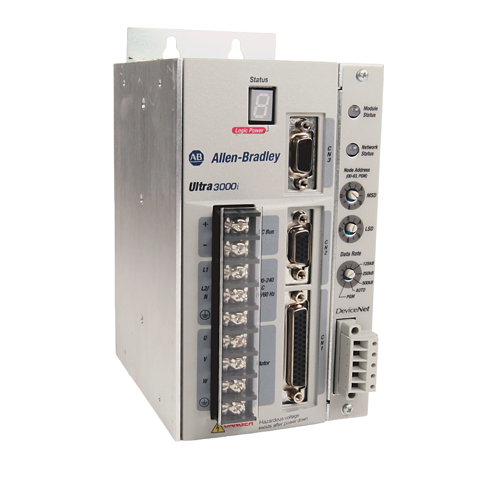
The Allen-Bradley 2098 Ultra 3000 digital servo drives are designed to provide flexible and precise motion control across a wide range of industrial applications. These drives support multiple communication interfaces—including analog, DeviceNet, SERCOS, and standalone modes—making them adaptable to different control systems. With models available in both 200V and 400V classes and output power ratings from 0.5 kW up to 22 kW, the Ultra 3000 line is well-suited for everything from small machinery to larger automation equipment.
Each drive is equipped to handle various feedback types, including incremental and absolute encoders, enabling highly accurate positioning and speed control. Fast digital response rates and integrated safety features also contribute to efficient and reliable operation. While the Ultra 3000 series has been phased out in favor of newer Allen-Bradley Kinetix platforms, it remains widely used in legacy systems. For facilities still running these drives, understanding their capabilities and available replacement options is essential for long-term support and system compatibility.
Quick Menu
- → Allen-Bradley 2098 Ultra3000 Servo Drive Selection Chart
- → Essential Components of the 2098 Ultra3000 Servo Drives
- → Step-by-Step Guide to Installing a 2098 Ultra 3000 Servo Drive
- → Testing and Maintenance of the 2098 Ultra3000 Drive
- → Troubleshooting Common 2098 Ultra3000 Servo Drive Issues
- → Spec Sheet
- → FAQ
Allen-Bradley 2098 Ultra3000 Servo Drive Selection Chart
The selection chart below condenses the Ultra3000 lineup into an at-a-glance reference. Review the voltage class, power rating, current limits, and interface options to pinpoint the exact drive your motor and control network require. Matching these core specs up front prevents overloads, wiring changes, and tuning headaches later.
| Catalog No. | Voltage Class | Cont. Power (kW) | Cont. Current (A rms) | Peak Current (A rms) | Interface Options* |
|---|---|---|---|---|---|
| 2098-DSD-005 | 200 V | 0.5 kW | 1.8 | 5.3 | Analog / SE / DN / X |
| 2098-DSD-010 | 200 V | 1.0 kW | 3.5 | 10.6 | Analog / SE / DN / X |
| 2098-DSD-020 | 200 V | 2.0 kW | 7.1 | 21.2 | Analog / SE / DN / X |
| 2098-DSD-030 | 200 V | 3.0 kW | 10.6 | 21.2 | Analog / SE / DN / X |
| 2098-DSD-075 | 200 V | 7.5 kW | 24.7 | 53 | Analog / SE / DN / X |
| 2098-DSD-150 | 200 V | 15 kW | 45.9 | 106 | Analog / SE / DN / X |
| 2098-DSD-HV030 | 400 V | 3 kW | 5.0 | 9.9 | Analog / SE / DN / X |
| 2098-DSD-HV050 | 400 V | 5 kW | 7.8 | 15.6 | Analog / SE / DN / X |
| 2098-DSD-HV100 | 400 V | 10 kW | 16.3 | 32.5 | Analog / SE / DN / X |
| 2098-DSD-HV150 | 400 V | 15 kW | 24.0 | 48.1 | Analog / SE / DN / X |
| 2098-DSD-HV220 | 400 V | 22 kW | 33.2 | 66.5 | Analog / SE / DN / X |
*Interface suffixes: SE = SERCOS, DN = DeviceNet, X = Standalone Indexing (add DN for indexing + DeviceNet).
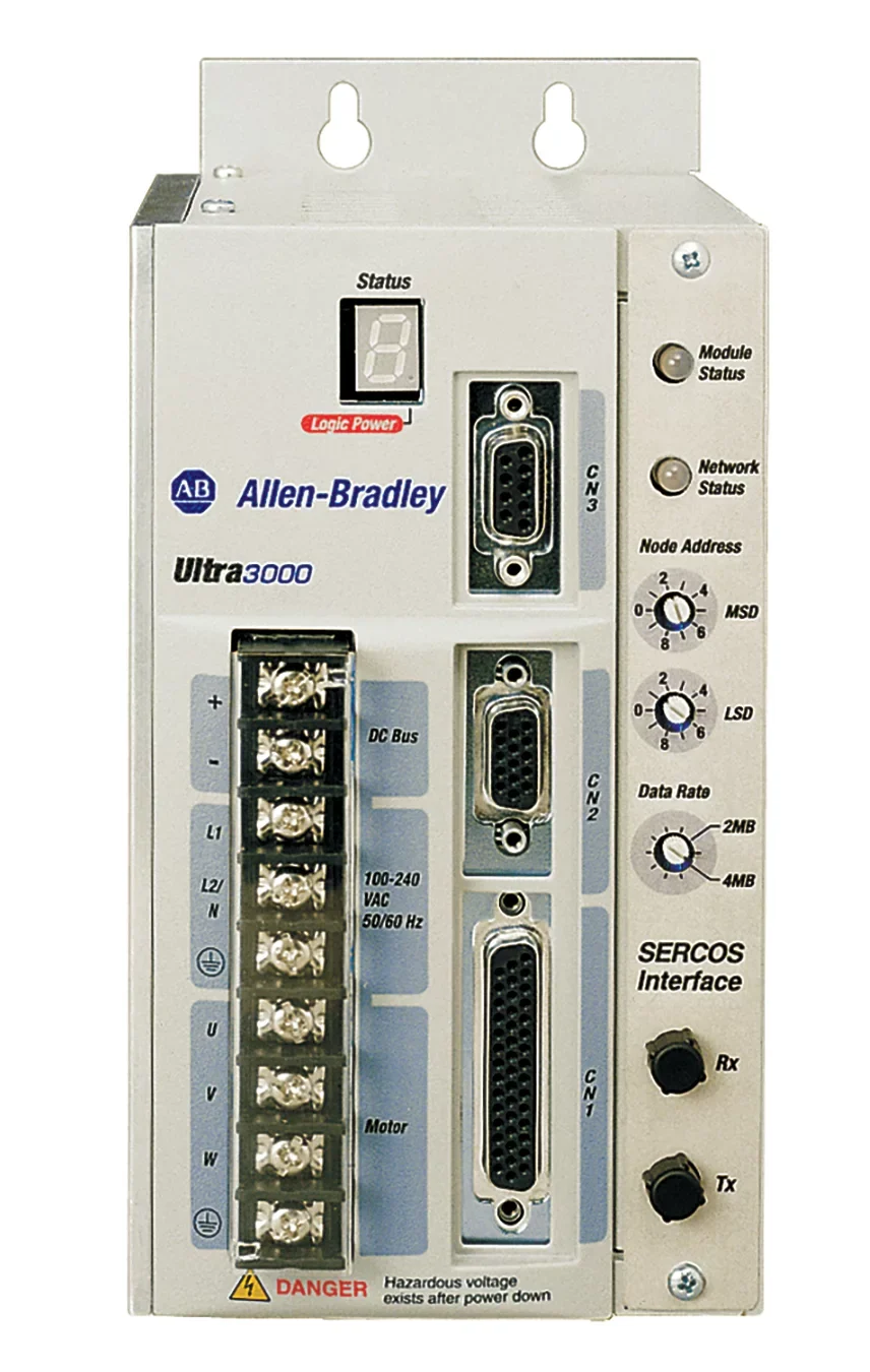
Essential Components of the 2098 Ultra3000 Servo Drives
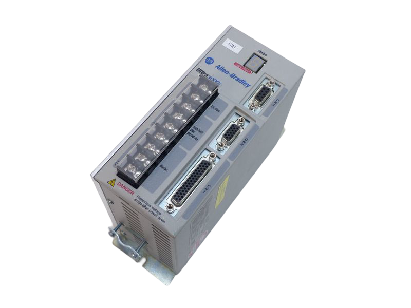
The essential components of the Allen-Bradley 2098 Ultra 3000 digital servo drives include several integrated systems designed to deliver precise, high-performance motion control. Here’s a breakdown of the key components:
Power Stage
- Converts AC input power to controlled voltage for the servo motor
- Handles voltage levels (typically 230V or 460V) and output currents for motors ranging from 0.5 kW to 22 kW
Control Logic Board
- Executes the digital motion control algorithms
- Manages positioning, speed, and torque regulation
- Interfaces with command sources (e.g., analog input, DeviceNet, SERCOS, indexing)
Digital Regulator
- Provides high-speed updates for current, velocity, and position loops
- Ensures accurate and stable motor performance
Feedback Interface
- Supports multiple feedback types:
- Incremental encoder
- Absolute encoder (SSI, EnDat)
- Sine/Cosine encoders
- Enables precise monitoring of motor position and speed
Communication Interface
- Varies by model (e.g., SERCOS, DeviceNet, standalone indexing, analog)
- Facilitates integration into a PLC or motion controller network
I/O Terminals
- Digital and analog inputs/outputs for external devices (limit switches, sensors, interlocks)
- Allows control logic customization and interaction with external systems
Internal Braking Circuit
- Absorbs excess regenerative energy during deceleration
- May include provisions for external braking resistors
Display/Status Indicators
- LED indicators for power, status, fault, and communication
- Some models include basic diagnostic displays or support an external HIM module
Protective Features
- Overvoltage, undervoltage, overcurrent, and short-circuit protection
- Thermal monitoring for drive and motor protection
Step-by-Step Guide to Installing a 2098 Ultra 3000 Servo Drive
1. Select the Correct Drive Model
- Identify the motor voltage and power requirements.
- Choose the correct 2098 drive based on:
- Voltage class (200V or 400V)
- Continuous and peak current ratings
- Command interface (Analog, DeviceNet, SERCOS, Indexing)
2. Choose a Compatible Servo Motor
- Select an Allen-Bradley servo motor that matches the drive’s specifications.
- Ensure the motor’s feedback device (incremental, absolute, sine/cosine) is supported by the selected drive.
3. Install the Drive
- Mount the drive vertically in an enclosure with proper ventilation.
- Maintain minimum clearance as per the installation manual.
- Follow appropriate grounding and shielding practices.
4. Wire Power Connections
- Connect the three-phase AC input to the L1, L2, and L3 terminals.
- Wire the motor output to U, V, W terminals on the drive.
- Connect a braking resistor if required for your application.
5. Connect Feedback Devices
- Plug the motor’s feedback cable into the encoder input port.
- Configure the feedback type in the software if required.
6. Connect Control Interfaces
- Wire the digital and analog I/O signals to the terminal block (e.g., enable, limit switches, home sensor).
- Connect the communication cable (DeviceNet, SERCOS fiber, or analog signal) to your control system.
7. Configure the Drive
- Use RSLogix or UltraWare software to:
- Set up motor parameters
- Define the control mode (velocity, torque, position)
- Assign I/O functionality
- Configure feedback and scaling
8. Test the Setup
- Power on the system.
- Observe status LEDs to ensure proper operation.
- Use software tools to jog the motor and confirm correct direction, feedback, and braking.
9. Tune the Drive
- Perform auto-tuning or manually adjust gain values to optimize performance.
- Monitor for overshoot, oscillation, or instability.
10. Finalize and Monitor
- Secure all wiring and check for EMI interference.
- Set operational limits (e.g., speed, torque, travel range).
- Begin production testing under real conditions and monitor for faults or overheating.
Testing and Maintenance of the 2098 Ultra3000 Drive
Testing and maintaining an Allen-Bradley 2098 Ultra3000 digital servo drive is essential for ensuring long-term system reliability and performance. Routine testing should begin with visual inspections—check for loose wiring, signs of overheating, dust buildup, or damaged connectors. Power on the system and observe the drive’s status LEDs for normal operation or diagnostic fault codes. Using UltraWare software, you can monitor key performance indicators such as output current, feedback signals, and system temperatures in real time. If the drive operates in a closed-loop configuration, verify that the feedback device is functioning correctly and that the motor reaches commanded positions with minimal error.
For preventative maintenance, regularly clean the drive and surrounding enclosure to prevent thermal issues caused by dust accumulation. Inspect cooling fans and ventilation for airflow obstructions, and check for any abnormal noises or vibrations during operation. Periodically back up the drive’s configuration parameters, especially before firmware updates or system changes. For drives operating in high-duty or critical environments, consider thermographic scanning to detect early-stage component fatigue. By maintaining a scheduled testing and maintenance routine, facilities can avoid costly unplanned downtime and extend the service life of their 2098 Ultra3000 servo drive systems. Always follow Rockwell Automation’s safety and handling guidelines during any maintenance activity.
Troubleshooting Common 2098 Ultra3000 Servo Drive Issues
- Drive Won’t Power Up: Check incoming AC power supply, fuses, and circuit breakers. Verify correct wiring and grounding.
- Fault LED is On: Connect to UltraWare software to view fault code. Refer to the fault table in the manual for specific diagnostics.
- Motor Not Moving: Verify enable signal is present. Check for active faults, correct command input, and ensure drive is not in a disabled or safe state.
- Erratic Motor Behavior: Inspect feedback cable and motor wiring. Recheck tuning parameters and ensure no electrical noise is interfering with control signals.
- Overvoltage Fault: Ensure braking resistor is properly sized and connected. Check for regenerative energy during deceleration or high-speed stops.
- Undervoltage Fault: Inspect incoming power for brownouts or voltage drops. Confirm stable supply within the rated input range.
- Overtemperature Fault: Ensure proper ventilation around the drive. Clean dust from heatsinks and verify cooling fans are operational.
- Feedback Loss or Encoder Error: Check encoder cable for secure connections. Verify correct feedback type is configured in UltraWare.
- Communication Failure: Ensure correct cabling and termination (for DeviceNet or SERCOS). Confirm node ID and baud rate match system settings.
- Indexing Doesn’t Start: Confirm trigger input is active and indexed program is correctly configured in software. Check I/O wiring and status.
Frequently Asked Questions – 2098 Ultra3000 Servo Drive Series
1. What types of control modes are supported by the Ultra3000 drives?
The 2098 Ultra3000 series supports multiple control modes, including torque, velocity, and position control. It also offers standalone indexing capabilities and supports command interfaces such as analog, DeviceNet, and SERCOS.
2. Can I use the Ultra3000 drive with third-party motors?
While Allen-Bradley recommends using Ultra3000 drives with Rockwell Automation motors for full compatibility, the drive can work with third-party motors if their electrical and feedback specifications match the drive’s supported ranges.
3. What feedback types are compatible with Ultra3000 drives?
Ultra3000 drives support several encoder types, including incremental, absolute (SSI, EnDat), and sine/cosine encoders. The correct feedback type must be configured in the drive software.
4. Has the Ultra3000 series been discontinued?
Yes, the Ultra3000 series has been discontinued by Rockwell Automation. However, it is still widely used in legacy systems and supported through parts, documentation, and migration tools.
5. What software is used to configure the Ultra3000 drives?
Ultra3000 drives are configured and tuned using Rockwell Automation’s UltraWare software, which provides tools for parameter setup, motor tuning, diagnostics, and monitoring.