In this guide, we will discuss all about the Honeywell RM7800 Burner Control. Which amplifiers work with each relay module, along with the timing card and wiring subbase options. We will also take a look at the flame sensors, how to match them with the control and amplifier, and how to install them.
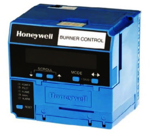
The Honeywell RM7800 series is a widely used primary burner control system designed for managing commercial and industrial burner operations with high reliability and safety. As a microprocessor-based system, the RM7800 provides automated sequencing, safety checks, and flame supervision for burners used in heating, power generation, and process applications. Its significance lies in its flexibility, diagnostics, and modular design, making it suitable for a wide range of burner configurations while ensuring compliance with safety standards.
Popular models include the RM7890C1005, RM7890B1014, RM7895A1014, RM7890A1015, and the RM7800L1012.
One of its key features is its plug-in modularity, which allows users to customize and expand the system based on specific burner requirements. The amplifier module determines the type of flame sensor used and enabling real-time flame signal processing. The subbase serves as the mounting platform, providing electrical terminations for easy wiring and installation. The flame scanner is essential for monitoring the burner’s flame presence, ensuring reliable ignition and sustained operation. Additionally, timing cards allow operators to adjust purge, pilot trial, and main flame stabilization timings, enhancing efficiency and adaptability.
By incorporating these accessories, the RM7800 ensures enhanced burner control, streamlined troubleshooting, and comprehensive safety monitoring, making it a preferred choice in demanding industrial environments where precise burner management is essential.

Choosing the Right Amplifier for Honeywell RM7800 Burner Controls

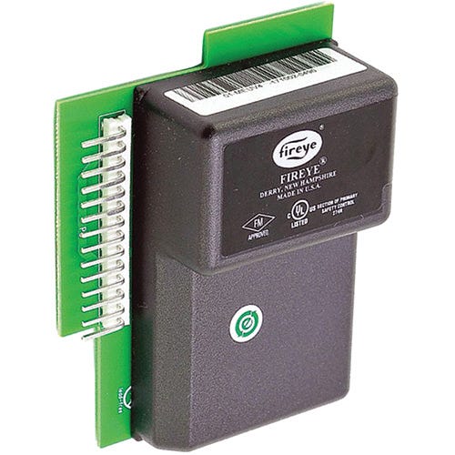
The Honeywell RM7800 burner control system relies on flame amplifiers to process signals from flame scanners, ensuring reliable flame detection and system safety. Selecting the right flame amplifier is crucial for proper burner operation, as A-models and B-models are not interchangeable. The correct amplifier must match both the flame scanner type and the burner control unit.
Types of Honeywell Flame Amplifiers for RM7800
- R7847A – Compatible with rectification-type flame rods. This is ideal for gas burners that use a flame rod for direct flame sensing.
- R7848A – Designed for use with C7027, C7035, and C7044 ultraviolet (UV) flame scanners. Suitable for applications where UV detection is required to verify the presence of a stable flame.
- R7849A – Used with rectification-type flame rods or self-checking UV scanners, making it versatile for certain industrial burner applications.
- R7851B – Specifically designed for C7061A1053 self-checking UV scanners, providing continuous monitoring of the scanner’s health for enhanced safety in critical applications.
- R7861A – Works with Honeywell C7076 infrared (IR) flame scanners, ideal for applications where distinguishing between pilot and main flames is necessary.
How to Choose the Right Flame Amplifier
To select the correct amplifier for your RM7800 burner control, follow these steps:
- Identify the Flame Scanner: The type of flame scanner in use determines the amplifier. For example, a C7027 UV scanner requires an R7848A amplifier, while a C7061 scanner requires an R7851B.
- Ensure Compatibility: A-model amplifiers (e.g., R7848A) cannot be used if a B-model amplifier (e.g., R7851B) is in the system. Mixing amplifier types can lead to incorrect flame detection.
- Consider Safety Requirements: If a self-checking UV system is needed for high-safety applications, an R7851B amplifier with a C7061 scanner is recommended.
Selecting the Best Subbase for Honeywell RM7800
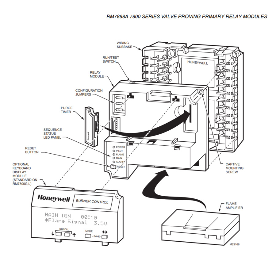 The subbase is a critical component of the Honeywell RM7800 burner control system, serving as the foundation for the burner control module and providing essential electrical connections. It ensures proper integration of the RM7800 with amplifiers, flame scanners, safety interlocks, and field wiring, making it an essential part of system reliability and performance.
How the Subbase Components Fit into the RM7800 System
The subbase acts as the primary wiring interface, connecting the RM7800 control module to external burner components. It has clearly labeled terminals for:
- Power input (line voltage and control voltage)
- Flame scanner connections for monitoring flame presence
- Burner control outputs (such as pilot valve, main valve, and blower motor)
- Limit and interlock circuits to integrate safety devices like pressure switches and airflow sensors
- Communication terminals for diagnostics and system monitoring
Once installed, the RM7800 control module plugs directly into the subbase, ensuring a secure and organized connection between all burner system components. This modular design simplifies maintenance and troubleshooting, as the control module can be replaced without rewiring.
Key Specifications to Consider for Effective Results
- Model Compatibility – Ensure the subbase matches the specific RM7800 model. Common subbase models include:
- Q7800A1005 (standard subbase for most RM7800 models)
- Q7800B1013 (includes additional relays for expanded burner control)
- Voltage Requirements – Confirm the subbase supports the appropriate power input (typically 120V or 220V AC).
- Terminal Configuration – Check that the terminal layout matches your burner control needs, including safety interlocks, flame scanner inputs, and fuel valve outputs.
- Wiring Capacity – Ensure the subbase provides enough terminals for all field connections, preventing overcrowded wiring that could lead to faults.
- Environmental Considerations – For high-temperature or vibration-prone environments, ensure the subbase is mounted securely and within a suitable enclosure to protect against electrical interference or mechanical damage.
Selecting the Flame Scanner for Honeywell RM7800

How the Flame Scanner Fits into the RM7800 System
The flame scanner connects to the RM7800 control module via the flame amplifier. The amplifier processes the scanner’s signal and determines whether the flame is present, stable, and safe to maintain burner operation. The RM7800 then activates or deactivates burner components (such as pilot valves and main fuel valves) based on this input. Different scanner types are used based on the burner’s fuel type, flame characteristics, and application requirements.
Key Specifications to Consider for Effective Results
- Flame Scanner Type – Choose a scanner that matches your flame characteristics and RM7800 system requirements:
- C7027, C7035, C7044 (UV Scanners) – Detect ultraviolet (UV) radiation from gas flames; ideal for clean-burning gas burners.
- C7061 (Self-Checking UV Scanner) – Provides continuous monitoring, required for high-safety applications where self-checking functionality ensures proper scanner operation.
- C7076 (Infrared Scanner) – Detects infrared (IR) radiation from oil and coal flames, effective for applications with flames that produce minimal UV radiation.
- Amplifier Compatibility – Each scanner type requires a corresponding flame amplifier to function correctly:
- UV scanners (C7027, C7035, C7044) → R7848A amplifier
- Self-checking UV scanner (C7061) → R7851B amplifier
- Infrared scanner (C7076) → R7861A amplifier
- Mounting Position and Alignment – Proper positioning ensures uninterrupted flame detection:
- The scanner must have a clear line of sight to the flame.
- Avoid excessive heat exposure (use heat-resistant mounts if necessary).
- Position away from external light sources to prevent false readings.
- Wiring and Electrical Specifications – Ensure proper connection with the subbase terminals:
- Use the correct voltage (typically 120V AC or 220V AC, depending on the model).
- Shielded cables may be necessary to reduce electrical interference in high-noise environments.
- Environmental Durability – Select a scanner suited for the burner environment:
- High-temperature areas require scanners with cooling capabilities or protective housings.
- Vibration-prone environments may need additional mounting stability to prevent misalignment.
Understanding Honeywell RM7800 Burner Control Displays

The Honeywell RM7800 supports various display modules to enhance user interaction and diagnostics. The S7800A Keyboard Display Module provides a 2-line LCD screen for real-time burner status, fault codes, and system parameters, enabling quick troubleshooting. The S7810A Data ControlBus Module allows for remote monitoring and data logging, improving operational insights. The S7820 Remote Display offers off-panel viewing, ideal for hard-to-access installations. These displays improve usability, reduce downtime, and simplify diagnostics, making burner management more efficient. Choosing the right display depends on accessibility, data needs, and remote monitoring requirements.

Finding Suitable Timing Cards for Honeywell RM7800

Timing cards in the Honeywell RM7800 burner control system allow users to customize burner sequencing and safety timing parameters, optimizing performance for different burner applications. These plug-in cards control critical timing functions such as purge duration, pilot trial time, and main burner stabilization, ensuring safe startup and shutdown sequences. By adjusting these parameters, operators can balance safety, efficiency, and fuel economy based on system requirements. The Honeywell ST800QA1039 is the most standard option, and always in stock.
Selection Guide for RM7800 Timing Cards
Standard vs. Custom Timing
- ST7800A – Provides default Honeywell timing values for general burner applications.
- Custom Timing Cards (ST7800B, C, D, etc.) – Offer different preset time delays to match specific burner needs.
Purge Time Considerations
- Short Purge (30-60 seconds) – Suitable for smaller burners with frequent cycling.
- Long Purge (90-240 seconds) – Required for larger systems needing thorough air exchange before ignition.
Pilot Trial Time and Main Flame Stabilization
- Shorter trial times (4-10 sec) reduce startup fuel waste but require reliable ignition.
- Longer trials (10-15 sec) accommodate burners with slow ignition characteristics.
Ensuring component compatibility within the Honeywell RM7800 system is crucial for safety, reliability, and optimal performance. Each component—flame amplifier, scanner, subbase, timing card, and display module—must align with the RM7800 model to function correctly. Mismatched parts can lead to faulty flame detection, incorrect sequencing, or system failures.
Tips for Integrating New Components:
- Check Model Compatibility – Verify part numbers match RM7800 specifications.
- Match Flame Scanner and Amplifier – Use the correct amplifier for the scanner type (e.g., C7027 UV scanner → R7848A amplifier).
- Review Timing Requirements – Select an appropriate timing card for burner sequencing.
- Test Before Full Integration – Conduct trial runs to ensure seamless operation.